Tl;dr: I bought an aftermarket power door lock/keyless entry kit. It went really well but it took a lot of time to install it.
My van had factory power door locks at one point, but by the time I got it, it did not. Despite extensive troubleshooting, I was never able to pinpoint the root cause. I decided to add an aftermarket keyless entry system, which ultimately solved that problem while giving me a wireless unlock key fob in the process.
I should warn you that if you go the exact route that I did, you’re in for a lot of work. I put at least 20 hours into the project by the time I was all done, and I didn’t even bother adding a lot of the bells and whistles such as the headlight blink function. Having said all that, I’m glad I decided to go through with it, since it turned out beautifully.
The way these kits work is relatively simple. You have a control box, a master actuator, and three secondary actuators. The master actuator goes in the driver’s door and it doubles as a switch. So when you manually lock and unlock that door, without using the wireless key fob, it sends a signal to the controller telling it to actuate the other three door locks. The master actuator accordingly has five wires going to it, while the secondary actuators each have only two. The secondary actuators are controlled by applying 12 V to one lead and ground to the other for half a second. They are actuated the other way by applying the reverse voltage. So, the secondary actuators only require two wires each.
How to add a wireless key fob if your power lock system works
This is not what I did, but it’s very easy. All you need is the wireless receiver/control module and the driver’s door actuator, which also incorporates a switch, and has five wires going to it. Unfortunately, to get the key fob you’ll probably have to buy a four-actuator kit and just not use any of the secondary actuators, but the kit still only costs $34 as of this writing, so other than being a bit wasteful this is not a huge deal. UPDATE: This system failed on me within less than a year, and the manufacturer is completely unresponsive to my requests for help. I do NOT recommend the same system that I used.
When you dig into the driver’s door, you’ll find that the driver’s door lock knob is connected by a linkage to a switch, which is very confusingly labeled an “actuator” if you look up the list of parts for that door. It’s a switch, NOT an actuator. It controls the other four locks.
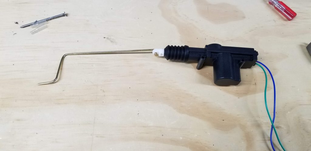
To add wireless functionality, you need to install the new master actuator in the door, above the latching mechanism, pointing upwards, so that it’s actuating in the same direction as the door lock knob, and couple it to the rod that connects the knob to the lock mechanism below. Then you need to find a place to install the control box, connect it to your battery and ground, and finally run the wires out into the door to connect it to the master actuator. The wires likely have to be extended unless you mount the control box inside the door itself, but I would recommend mounting it inside the vehicle and extending the wires instead. I describe how I did all of those steps and more in the following sections.
What you would end up with following this approach is a new piggyback system that is stimulating your existing power lock system by automatically moving the driver’s door lock knob up and down. The rest of the lock system is left intact and now you have a wireless key fob. This could be done in one afternoon if you have all the tools and supplies ready to go.
How to add a wireless key fob and power locking if your power lock system is broken or nonexistent
This is technically easy, but labor-intensive. I would estimate I put about 20 hours’ worth of labor into it over the course of a week.
Tools needed
- Step drill bit
- Wire strippers
- Soldering tools (soldering iron, tip cleaner, butane torch, helping hands)
- Caulk gun
- Stiff wire for wire-pulling, such as from a coat hanger or 14 GA solid core wire (commonly used for residential wiring)
Consumables needed
- Power door lock kit
- Solder (lead-based preferred, wash your hands after using it)
- Soldering flux paste (optional but recommended)
- Heat shrink tubing
- Cutting fluid
- Silicone sealant/caulk
- Electrical tape
Familiarizing yourself with the new harness
What you are effectively doing with this project is running a brand new wiring harness in parallel with your existing harness. To some degree you will be able to re-use the existing wires in the sliders and the hatch if you’re doing a full install in a van.
Lay out the harness that comes with the kit. You will find a purple wire that can be used to make the headlights blink* (optional) and a brown and white wire which can be used to install a separate switch inside the vehicle which activates the central lock/unlock function (also optional). I have not connected either to anything as of this writing. You will also find a bundle of five wires that go to the driver’s door, and three pairs of green and blue wires which are intended to go to the secondary door lock actuators. The green and blue wires pairs are all different lengths. Sort them by length, and label each pair with where it needs to go. The shortest should go to the front passenger door, medium length one should go to the sliders, and longest to the hatch.
*NOTE: These vehicles are ground-switched, which means that accessories like the headlights are wired to constant hot 12 VDC, and are turned on by connecting them to ground. All cars made today work the opposite way, where all the accessories are grounded by default and 12 VDC is applied to make them turn on. These power lock kits assume you have a modern system, so if you really want to make your Sambar’s lights blink when you unlock it, you’ll also need to install a conversion kit first. I do intend to do this eventually so I can install LED headlights, but as of this writing I haven’t gotten to it yet.
Taking the car apart
Remove the front door inner panels: First, remove the single screw in the pull handle. Next, remove the door opening handle by pushing the panel inward and pulling the retaining clip out radially. I used a curved pick for this. Be careful not to lose this clip — definitely don’t do this job with the vehicle parked on gravel. Now pop the panel loose all around the sides and bottom by pulling firmly, and finally work it up and over the lock knob to free it. You will then need to disconnect the wires that go to the power window switches. A small flat head screwdriver helps to get the connectors separated; this was the worst connector I had to deal with in the whole job.
Remove the front seats: This involves two latches in front on the passenger seat and two 12 mm-head screws in the back, and four 12 mm-head screws on the driver seat. Remove the battery cover and disconnect the positive terminal while you’re at it.
If you’re modifying a van, also do the following:
- Remove the right rear taillight assembly to expose two electrical connectors behind it.
- Remove the inner panel from the hatch by pulling firmly around the edge.
- Pull back the right panel in the cargo area to allow access behind the right taillight for wire routing.
Mounting the control box
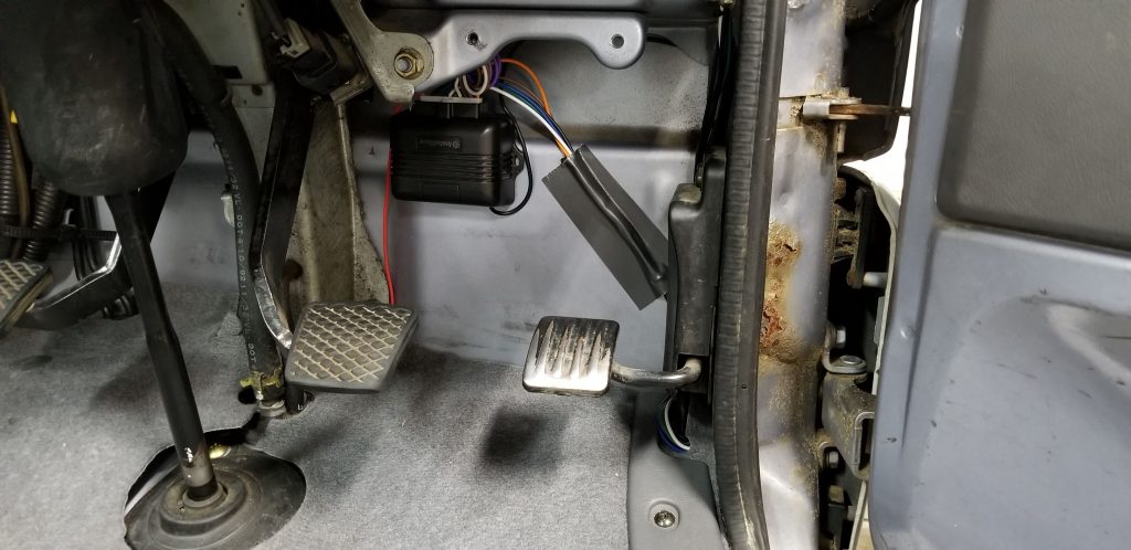
This can go anywhere in the front region of the vehicle. I mounted mine behind the brake pedal using the supplied double-sided adhesive pad. This was mainly to prevent me from having to extend the wires to the master actuator, but in the end I had to extend them anyway. If I were to do it all over again, I would mount it under the driver’s seat instead.
Routing wires into the driver’s door
This was probably the most challenging part of the project. You cannot simply pass the wires through the existing grommets. You’ll see what I mean when you get into it.
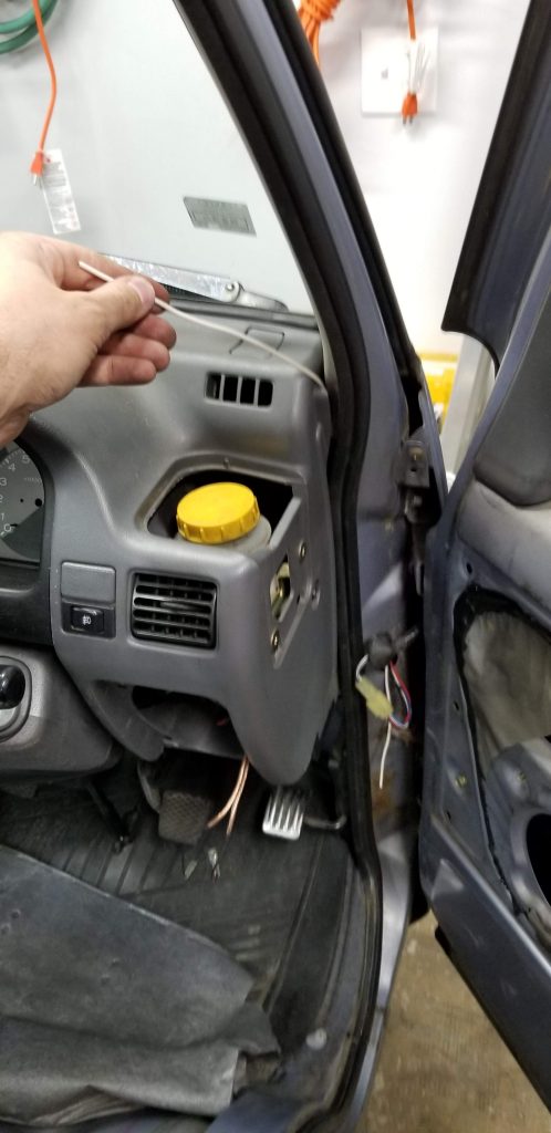
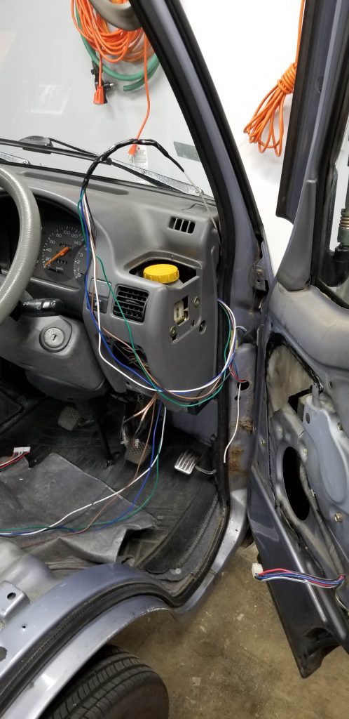
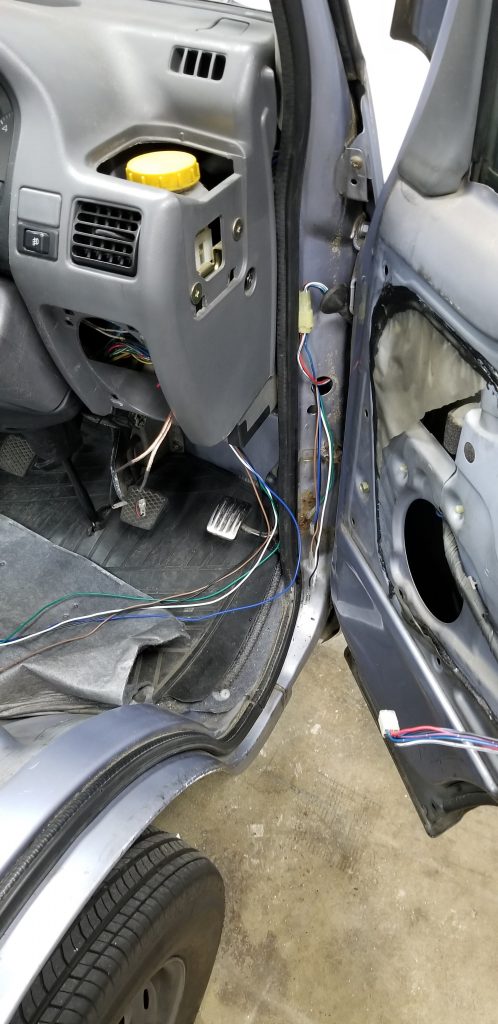
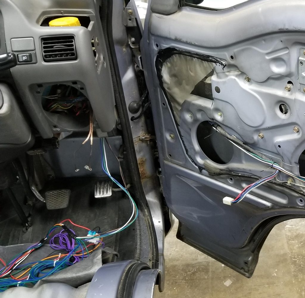
To get the wires from the control box and out of the vehicle, I ran them up behind the front brake fluid reservoir, following four of the wires that go out through the stock grommet to the door. These wires go up almost all the way to the windshield, then make a U-turn to the right and head down through the inner cavity of the car’s unibody, before finally emerging through the stock grommet. First I pulled out the vehicle-side stock grommet which revealed only four wires. Confusing, because there are a total of six that go into the door. The other two come from behind the front bumper somewhere. Anyway, I pulled that grommet out and then pulled the wires and their connector out to make sure there was nothing behind the sheet metal there. Then I drilled a new hole in the vehicle body (not the door) below the grommet hole with a step bit. Okay, now forthe hard parts.
Hard part 1 of 2: I used a piece of stiff wire I had left over from a home improvement wiring project as a guide wire to find the path the existing wires take from behind the brake fluid reservoir down to the grommet. This took quite a while. Then, I taped the five wire ends that will go to the master actuator together to form a “bullet” using electrical tape. The key here is to stagger the ends so that the bullet is tapered, with only one connector at the tip, and getting progressively thicker as you go.
I pushed the bullet up from the footwell area, upward behind the brake fluid reservoir, and through the crack between the dash and the vehicle body. I then taped the bullet to the end of the guide wire, and carefully pulled it down into the car body, feeding the other end upwards as I went. Finally the bullet came all the way down through until it was hanging out of the stock grommet opening. I unwrapped all the tape and dismantled the bullet, and then carefully fed each wire through the new hole I had drilled below the stock grommet opening.
Hard part 2 of 2: There is no clearance to drill a new hole in the door to get these wires into it. You’d have to remove the whole door, which wasn’t in the cards. Instead, I was able to pass these wires through the stock grommet. I managed this by using an Xacto knife to cut a slot in the rubber diaphragm that seals the six wires going through the door-side stock grommet, then individually forcing each of the five wires through that slot. This was painstaking but I eventually managed to get all the wires through.
Finally, I wrapped the wires together in electrical tape extensively to make a cable, and used silicone sealant/caulk to create a new grommet in the hole that I had drilled. Since it’s impossible to get access to the back side of that sheet metal to deburr the hole, I am relying on the silicone grommet to keep the new wire bundle from rubbing against the sharp edges and potentially cutting through the wire insulation. I left the door partially open overnight so that the silicone could cure and solidify before proceeding with any further work on that door.
Routing wires into the front passenger door
The stock actuator in this door is a 3-wire type, which is NOT compatible with your new central lock controller. If you are only installing the master actuator and your existing power door lock system works, you don’t need to do any of these steps, but if you’re doing the whole thing, you need to route new wires out to that door to control the new actuator you will install.
I took the shortest pair of green and blue wires and routed it toward the passenger footwell, running along the seam between the front of the body and the floor, behind the pedals. Then I went upwards and through an existing hole in the body. Like on the driver’s side, I had to drill a new hole, again first removing the stock grommet and pulling the wires out so that I didn’t drill through them. I routed the two wires through the door-side grommet through a slit I cut with my Xacto knife and created a new grommet using silicone. Still a bit of a pain but nothing like the driver’s side was.
Routing wires to the sliders
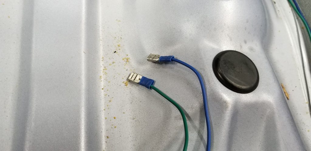
The stock actuators can be re-used as they are the 2-wire type. There are 2-pin connectors under the front driver and passenger seats which go to these. They eventually connect to the pair of contacts in the door well that the spring pins on the door engage with. On the door side, the connector wires are red and white. I disconnected the old connectors coming from the stock central locking circuit and connected the blue and green wires from the new harness using crimp spade terminal fittings/connectors. You should only use one pair of blue and green wires for this, and cut and solder them to form a T junction near the e-brake handle. Don’t worry about polarity too much; if you guess wrong, you can always just swap the spade connectors.
I strongly recommend thoroughly protecting each spade terminal with heat shrink. The two sides will be precariously close to each other and very likely to create a short circuit otherwise.
Routing wires to the hatch
The bad news with the hatch is that the existing actuator is a three-wire type and therefore cannot be reused easily. The good news is that it is easy to co-opt two of the wires that are already routed out to there for the existing lock actuator and use them for the new actuator.
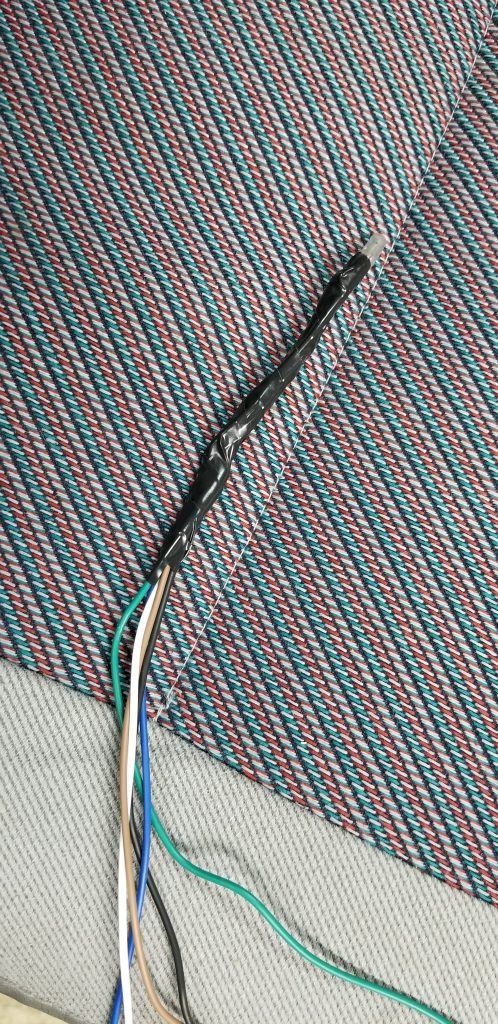
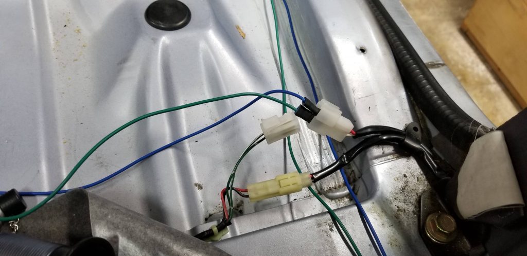
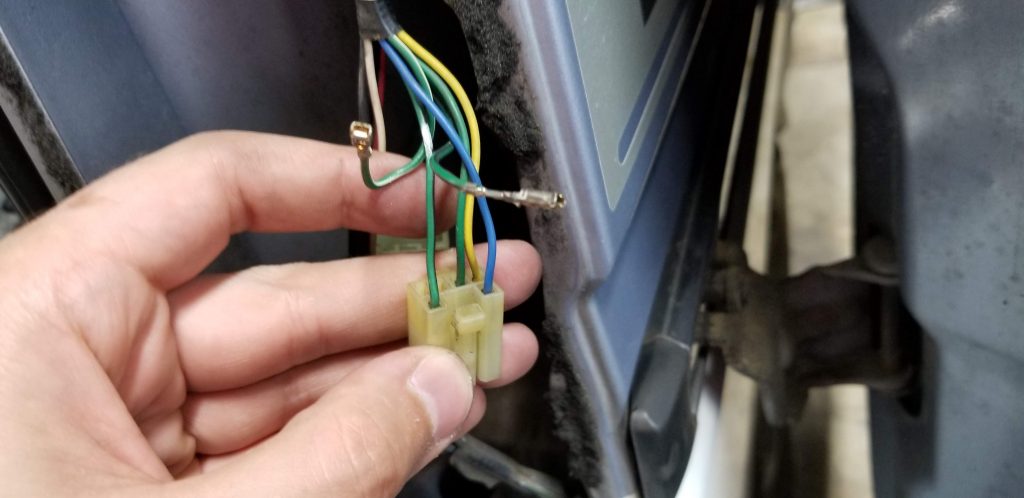
First, I disconnected the pair of connectors with 6 wires that lives behind the right taillight. This is either R33 or R34 in the electrical schematic. The wires you need to tap into are green with a white stripe and green with a black stripe. I will call these the “existing hatch wires” from here forward. Confusingly, there are two green-with-black-stripe wires in that connector. One is a ground. See the photo below.
To wire the hatch, I first routed the longest green and blue wire pair from the new harness out to the space behind the right taillight. I went down along the edge of the carpet that butts up against the sliders, then ducked behind the rear right interior panel, and finally through the inside of the body back to the taillight. There are undoubtedly other ways to route the wires but this was the easiest way that seemed like it would give a clean result.
Next, I extracted the two existing hatch wires identified above, then cut the ends off the new green and blue wires and soldered them to the existing wires. I recommend pulling the existing wires’ crimped-on pins out of the plastic connector shell and then clipping the pins off. It doesn’t matter which new wire you choose to solder to which old wire because you can always just flip the connectors at the actuator if you get it backwards the first time.
Inside the hatch, I located the actuator and unplugged it. I cut off the wires and figured out which ones go to the existing hatch wires behind the taillight. Then I soldered the ends of the green and blue wires onto these in preparation to connect them to the actuator.
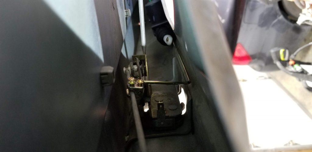
Mounting the actuators
First, I removed the stock actuators from the front passenger door and the hatch. The passenger door actuator is mainly held on with friction and will come off with some creative prying-it-with-a-screwdriver work. The one in the hatch comes off with two 10 mm hex-head screws. Do NOT remove the stock “actuator” from the driver’s door. It’s not necessary to remove it, whether you’re just trying to add keyless entry to an otherwise fully-functional power lock system, or doing the full replacement like I did.
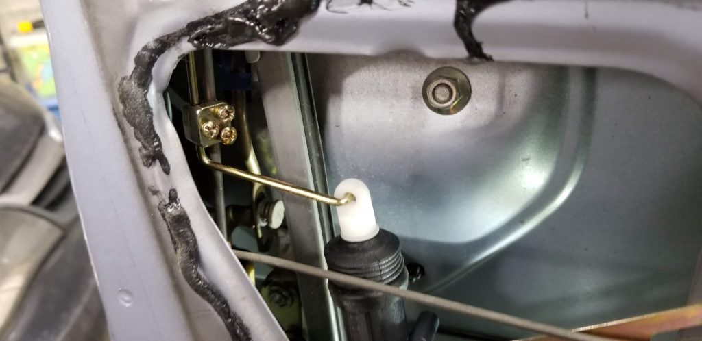
I’ll let the photos speak for themselves for the actuator installation. In the hatch you have a lot of freedom and the way I mounted mine is just a suggestion. In the front doors you have very limited options where the actuator will not hit the window when it rolls down. Mounted as shown, I have maybe 1 mm of clearance from the window to the actuator at the tightest spot. It works great but it’s very close to hitting.
You may notice in the hatch photos that I mounted a second actuator. I was trying to use it in conjunction with the 3rd button on the key fob to release the latch. The actuator does not have enough pulling force, unfortunately, so that was a dead end. I haven’t decided what I want to use the third button for, but it would be fun to hook it up to the horn or something like that.
Last steps
I connected the ground lead on the harness to a nearby ground point – there was already a screw in the vicinity being used to ground the fog lights, so I stacked the lug on top of that – and then connected the power supply lead to the positive terminal of the battery. Since I used these battery connectors I got on Amazon, I was able to easily add the new power wire using one of the side screw terminals on the connector. Make sure you disconnect the battery connector first! I also recommend doing this wiring with the new in-line fuse removed, and with the harness disconnected from the lock control box.
For the wires on the harness that I did not use – the brown and white ones for adding a lock/unlock button inside the car, and the purple one for making the lights blink – I clipped them to a few inches long and then curled them up and zip-tied them together.
Once I was happy with all of my wiring work, I plugged the harness into the control box and inserted the fuse. I grabbed one of the key fobs and gave it a try. All the locks worked! The only final change I had to make was to flip the wires on the hatch actuator, since my first guess was wrong.
Now that the system was completely installed and functional, I proceeded to button everything back up and put the whole interior back together. The only tough part was dealing with routing the wires around/under/through the accelerator pedal area, but I eventually tamed it and it ended up looking pretty good.
Overall I am extremely satisfied with the result. I even went out and bought a second door lock kit and installed the same system in my 1980 Chevy pickup truck a few weeks later. Edit: As of 2021-11-26, the keyless entry in the truck still works. The van’s currently does not work.